![]() Multi-Function Controller
Multi-Function Controller
Core(1PCS)-XA003
Buka ea Mosebelisi
Core-A11
Likaroloana
- 2.4Ghz wireless remote control, 10m control distance with an ultra-small size.
- High cost-performance ratio, suitable for car, ship, and tank models, etc.
- Provide up to 10 channels for connecting different devices.
- Phetolelo ea Phatlalatso Moqtage: 4.5V~12.6V(1S-3S), operating current: 65mA.
- Kenyelletso ea Moamoheli Moqtage: 7.4V-12.6V(2S-3S), standby current: 60mA, operating current: 200~300mA, maximum current: 3A.
- Support configuration on mobile phones& PCs, with a user-friendly interface.
Receiver & Transmitter Shield
Remote Control Transmitter Shield

On the left and right sides of the transmitter shield, there are 3 ADC input channels respectively. Below it, there are 4 digital input channels. The gray slot on the back is the slot for the multi-function controller core. It can be powered through the XH2.54 power input.
- ADC input port L1~L3,R1~L3: 3pin SH1.0 slot. Connectable with single/dual axis joystick module, three-position rocker switch module, etc.
- Digital input Port K1~K4: 2-pin SH1.0 slot. Connectable with a momentary button module, etc.
- XH2.54 DC power input: 2-pin XH2.54 slot. Connectable with a 4.5V~12.6V power supply.
Remote Control Receiver Shield

On the left and right sides of the receiver shield, there are, respectively, a DC motor port and a WS2812 port. In the center, there are 4 servo ports. It can be powered through the XH2.54 power input.
- DC Motor Port M1、M2: 2pin SH1.0 slot. Connectable with a DC motor, supporting forward and reverse rotation control& PWM speed regulation.
- WS2812 Port D1、D2: 3pin SH1.0slot. Connectable with WS2812 LED hubs or other light strips that use the WS2812 protocol.
- Servo Port S1~S4: 3-pin header. Connectable with universal 5V servo motors.
- Core Slot: A double-row gray slot. Connectable with a multi-function controller core.
- XH2.54 Power Input: 2-pin XH2.54 slot. Connectable with a 7.4V~12.6V power supply.
Multi-Function Controller Core
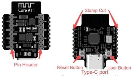
- Stamp Seha: Solderable Pinout. It allows users to solder leads to achieve customized circuit connections.
- Seta Botjha Konopo: Press to reset the main program.
- Konopo ea Mosebelisi: Custom Function.
- Mofuta oa C Port: Type-C Port. Connect to the PC via a data cable for programming and burning the program.
- Pin Header: Pin Header. Connectable with Shield.
Hardware connection between the controller core and the remote control transmitter/receiver shield
As shown in the figure, the controller core, the remote control receiver shield, and the remote control transmitter shield have antenna symbols. When making the connection, it is necessary to ensure that the orientations of these three symbols are the same and the pins correspond to each other one by one.
Orientations of these three symbols are the same.

Pins correspond to each other one by one.
Definition of the System Status Indicator
- Powered on but not connected: green light on
- Bluetooth connected: blue light on
- 2.4GHz connected: yellow light on
- Bluetooth& 2.4GHz connected: light flashes alternately between blue and yellow
- Profile upgrading: green light flashes at a frequency of 2Hz and continues until the transmission ends.
- Control object recognition: The green light flashes at a frequency of 1 Hz for 5 seconds.
Connect to the RC Transmitter & Receiver on the PC client.
Power the controller core through the Type-C port or the XH2.54 Power Port on the expansion shield.

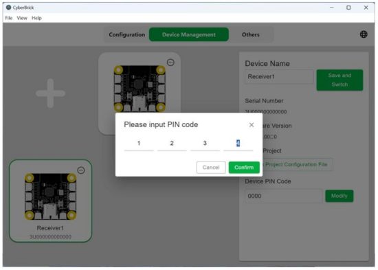
Run CyberBrick client, switch to Device Management

Click [+] to find your device

Connect the device by entering the PIN code. If the PIN hasn’t been set during the first connection, confirm directly.

After a successful connection, the indicator of the controller core lights blue, and the client displays this device.

Click on the expansion symbol in the upper right corner of the device. If you have connected multiple devices, click on Recognize, and the status indicator of the selected device will flash green; if you need to disconnect from the selected device, click on Disconnect.

Click on the device, and you can change the name of the device in the upper right corner to make it easier to identify it when there are multiple devices.

If you need to change the PIN code of the device, you can click Modify in the lower right corner and enter the new PIN code.
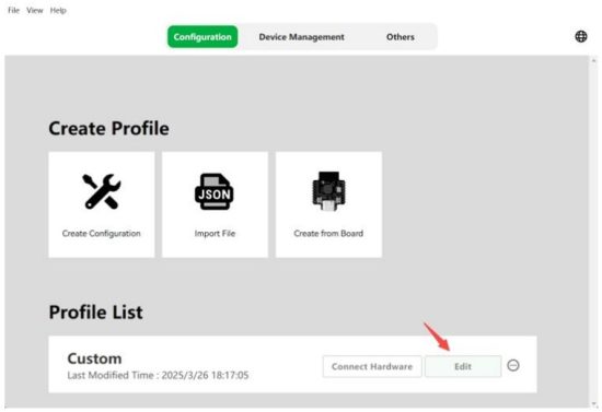
Configure the core controller profile
Click on the Configuration, click on Create Configuration, and start with a template, or an empty configuration[Custom].

Here we take the custom empty configuration as an example, click on Custom, and then click on Edit in the configuration list below.
After entering the configuration interface, first, click Add Receiver on the left side, and input the name of the receiver.
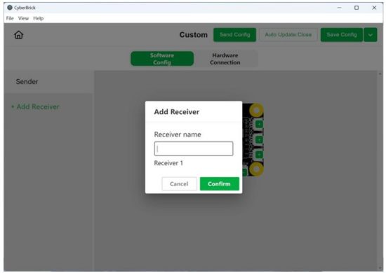
Click on the hardware connection above and drag the receiver device and controller device to the corresponding position.

Click to start pairing. After pairing successfully, the status indicators of these devices should flash blue and yellow alternately.

After modifying the configuration, remember to save the configuration locally with Save Config in the upper right corner, and update the configuration to the device with Send Config.
Lethathamo la melaoana e sebetsang ea FCC
Karolo ea 15.247 ea FCC
Leibole le lintlha tsa ho latela melao
FCC ID label on the final system must be labeled with “Contains FCC ID: 2A6J8-COREA11” or “Contains transmitter module FCC ID: 2A6J8-COREA11”.
Lintlha tse mabapi le mekhoa ea tlhahlobo le litlhoko tse ling tsa tlhahlobo
Contact Shenzhen Tuozhu Technology Co., Ltd. will provide a stand-alone modular transmitter test mode. Additional testing and certification may be necessary when multiple modules are used in a host.
Teko e eketsehileng, Karolo ea 15 Karolo ea B ea boitlhompho
Ho etsa bonnete ba ts'ebetso ea ts'ebetso ea mesebetsi eohle eo e seng ea li-transmitter, moetsi oa moamoheli o na le boikarabello ba ho etsa bonnete ba ho latela (li) module tse kentsoeng le ho sebetsa ka botlalo. Bakeng sa mohlalaample, if a host was previously authorized as an unintentional radiator under the Supplier’s Declaration of Conformity procedure without a transmitter-certified module and a module is added, the host manufacturer is responsible for ensuring that, after the module is installed and operational, the host continues to be compliant with the Part 15B unintentional radiator requirements. Since this may depend on the details of how the module is integrated with the host, Shenzhen Tuozhu Technology Co., Ltd. shall provide guidance to the host manufacturer for compliance with the Part 15B requirements.
Tlhokomeliso ea FCC
Sesebelisoa sena se lumellana le Karolo ea 15 ea Melao ea FCC. Ts'ebetso e ipapisitse le maemo a mabeli a latelang:
(1) Sesebelisoa sena se ka 'na sa se ke sa baka tšitiso e kotsi,' me (2) sesebelisoa sena se tlameha ho amohela tšitiso leha e le efe e amohetsoeng, ho kenyelletsa le tšitiso e ka bakang ts'ebetso e sa batleheng.
ELA HLOKO 1: Liphetoho leha e le life kapa liphetoho yuniting ena tse sa amoheloang ka ho hlaka ke mokha o ikarabellang bakeng sa tsamaiso li ka hlakola matla a mosebelisi a ho sebelisa sesebelisoa.
Polelo ea Ts'oaetso ea Mahlaseli a FCC:
This equipment complies with FCC radiation exposure limits set forth for an uncontrolled environment. End users must follow the specific operating instructions to satisfy RF exposure compliance.
Tlhokomeliso 1: This module is certified to comply with the RF exposure requirement under mobile or fixed conditions; this module is to be installed only in mobile or fixed applications.
A mobile device is defined as a transmitting device designed to be used in locations other than fixed locations and to generally be used in such a way that a separation distance of at least 20 centimeters is normally maintained between the transmitter’s radiating structure(s) and the body of the user or nearby persons. Transmitting devices designed to be used by consumers or workers that can be easily relocated, such as wireless devices associated with a personal computer, are considered to be mobile devices if they meet the 20-centimeter separation requirement.
Sesebelisoa se tsitsitseng se hlalosoa e le sesebelisoa se sirelelitsoeng 'meleng sebakeng se seng' me ha se khone ho isoa sebakeng se seng habonolo.
Tlhokomeliso 2: Any modifications made to the module will void the Grant of Certification. This module is limited to OEM installation only and must not be sold to end-users; end-user has no manual instructions to remove or install the device, only software or operating procedure shall be placed in the end-user operating manual of final products.
Tlhokomeliso 3: Mojule o ka sebetsoa feela ka antenna eo e lumelletsoeng ka eona. Lenakana lefe kapa lefe la mofuta o le mong le phaello e lekanang kapa e fokolang joalo ka lenakana le lumelletsoeng ka radiator ka boomo le ka rekisoa ka radiator, 'me la sebelisoa le radiator ka boomo.
Tlhokomeliso 4: For all products marketed in the US, OEM has to limit the operation channels in CH1 to CH11 for the 2.4G band by supplying a firmware programming tool. OEM shall not supply any tool or info to the end-user regarding to Regulatory Domain change.
IC TEMOSO
Sesebelisoa sena se na le li-transmitter tse sa ikenyeng laesense tse tsamaisanang le Innovation, Science and Economic Development RSS(li)laesense ea Canada e sa tsoeng. Ts'ebetso e ipapisitse le maemo a mabeli a latelang:
- Sesebelisoa sena se kanna sa se ke sa baka tšitiso.
- Sesebelisoa sena se tlameha ho amohela tšitiso efe kapa efe, ho kenyeletsoa tšitiso e ka bakang ts'ebetso e sa batleheng ea sesebelisoa.
IC Radiation Exposure Statement:
This device and its antenna(s) must not be co-located with any other transmitters except by IC multi-transmitter product procedures. Referring to the multi-transmitter policy, multiple-transmitter(s) and modules (s) can be operated simultaneously without reassessment permissive change.
Sesebelisoa sena se latela meeli ea ts'oaetso ea radiation ea IC RSS-102 e behetsoeng tikoloho e sa laoleheng. Sesebelisoa sena se lokela ho kengoa le ho sebetsoa ka bonyane ba 20cm lipakeng tsa radiator le 'mele oa hau.
This module is limited to OEM installation only and must not be sold to end-users; end-user has no manual instructions to remove or install the device, only software or operating procedures shall be placed in the end-user operating manual of final products. Additional testing and certification may be necessary when multiple modules are used.
Liphetoho leha e le life kapa liphetoho tse sa amoheloang ka ho hlaka ke moetsi li ka senya matla a mosebedisi a ho sebelisa thepa ena.
The end product must be labeled in a visible area with the following: “Contains IC: 28436-COREA11 “.
![]()
Multi-Function Controller Core

Litlhaloso tsa Sehlahisoa
| Nomoro ea Ntho | Karolo | Mosebetsi |
| 1 | W52812LED | RGB system status indicator |
| 2 | Stamp Khaola | Solderable pinout |
| 3 | Seta Botjha Konopo | Press to reset the main program |
| 4 | Boema-kepe ba Mofuta oa C | Burning firmware & programming |
| 5 | Konopo ea mosebelisi | Ts'ebetso ea moetlo |
| 6 | Pin Header | Connectable with various shields |
| 7 | Orientation Mark | Ensure proper installation alignment |
| ID ea sehlahisoa | EA-XA003 |
| Mohlala | Core A11 |
| Mofuta oa C oa Kenyeletso oa Molumotage | DC 5V |
| VBAT Input Voltage | 3.7V-12.6V |
| Mofuta oa Antenna | Antenna ea PCB |
| Remote Control Distance | Up to 100m (in open space) |
| Boima ba 'mele | 6g |
| Boholo | 27*22mm |
![]()
Litokomane / Lisebelisoa
 |
Tuozhu Core-A11 Multi Function Controller [pdf] Bukana ea Mosebelisi Core-A11, Core-A11 Multi Function Controller, Multi Function Controller, Controller |