
1. Selelekela le Ho Fetaview
The SMARTGEN CMM366A-ET Cloud Monitoring Communication Module is an Ethernet communication protocol switch module designed to connect gensets (with SCI) to the internet. After logging into a cloud server, the module receives the corresponding genset controller communication protocol. It acquires genset data via RS485, USB, LINK, or RS232 ports and transmits this data to the cloud server via wired Ethernet. This enables real-time monitoring of running status and access to historical records through mobile applications (iOS or Android) and PC terminal devices.
Beyond genset monitoring, the CMM366A-ET module also supports digital alarm input/output signals, allowing for monitoring of generator room access, theft prevention, and fire detection facilities.
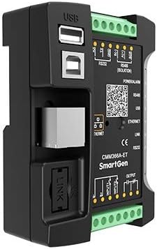
Setšoantšo sa 1: Pele view of the CMM366A-ET module, highlighting the USB, Ethernet, and LINK communication ports.

Setšoantšo sa 2: Ka pele e nang le angled view of the CMM366A-ET module, showing the communication ports and the row of LED indicators on the side.
2. Performance and Characteristics
- Connects to a cloud server via wired ETHERNET for one-to-one monitoring.
- Features multiple ports for communication with genset control modules: RS485, RS232, LINK, and USB (Host). Capable of monitoring a wide range of international first-class genset control modules.
- Wide power supply range: DC (8~35)V, allowing direct use of the genset's built-in starter battery.
- Equipped with an ARM-based 32-bit SCM for high hardware integration and strong programming capabilities.
- Includes a GPS locate function to acquire location information and track the genset.
- Utilizes JSON network data communication protocol, uploading real-time data variations with a compression algorithm to significantly reduce network traffic.
- Immediately uploads data to the server when an alarm occurs.
- Two auxiliary digital input ports are available for receiving external alarm signals.
- One auxiliary relay output port can output various alarm signals.
- Includes calendar and clock functions.
- Power and multiple communication status indicators on the front panel provide clear operational status at a glance.
- Features a lamp mosebetsi oa teko.
- Parameters can be adjusted via the USB port.
- Supports standard π-type 35mm guide-rail installation or screw-fixed installation, allowing flexible mounting within the genset control box.
- Modular design with a self-extinguishing ABS plastic shell, offering light weight, compact structure, and easy installation.
3. Litlhaloso
The following table details the technical specifications of the CMM366A-ET module:
| Ntho | Litaba |
|---|---|
| Tshebetso Voltage | DC 8.0V ~ 35.0V, phepelo ea motlakase e tsoelang pele |
| Tšebeliso ea Matla | Standby: ≤2W, Working: ≤5W |
| Input ea dijithale | Ho kenya Volt mahala tsa dijithale |
| Relay Output | 1A DC30V Volts e hlahisoang mahala |
| Moamoheli oa USB | Boema-kepe ba basali ba USB ba mofuta oa A |
| RS485 | Mofuta o ikhethileng |
| RS232 | Mofuta o akaretsang |
| LINK | SmartGen boema-kepe bo ikhethileng |
| Sesebelisoa sa USB | Boema-kepe ba basali ba USB ba mofuta oa B |
| Ethernet | RJ45 10/100Mbps sehokelo sa marang-rang se ikamahanyang le maemo |
| Litekanyo tsa Nyeoe | 72.5mm x 105mm x 34mm (hoo e ka bang lisenthimithara tse 4.13 x 2.87 x 1.38) |
| Maemo a Mosebetsi | Temperature: (-25~+70)°C, Humidity: (20~93)%RH |
| Boemo ba polokelo | Mocheso: (-25~+70)°C |
| Boima ba 'mele | 0.15kg (approx. 6.4 ounces) |
| Lintho tse bonahalang | Self-extinguishing ABS plastic |
4. Ho kenya le ho seta
4.1 Ho hloella
The CMM366A-ET module offers flexible installation options. It can be mounted using a standard π-type 35mm guide-rail (DIN rail) or via screw-fixed installation. This allows for convenient placement within a genset control box or other suitable enclosures.
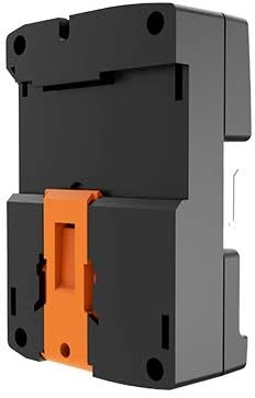
Setšoantšo sa 3: Ka morao view of the CMM366A-ET module, illustrating the integrated orange clip for DIN rail mounting.
4.2 Mehala le likhokahano
Proper wiring is essential for the correct operation of the CMM366A-ET module. Refer to the system diagram and terminal descriptions below for guidance.

Figure 4: CMM366A-ET System Diagram. This diagram illustrates how one CMM366A-ET module connects with one genset monitor module via RS485, LINK, RS232, or USB ports. The CMM366A-ET then connects to a router, which communicates with the cloud server, enabling monitoring via cellphone, tablet, or PC.
The CMM366A-ET module connects to a genset controller via one of its communication ports (RS485, LINK, RS232, or USB). It then connects to a network router via its Ethernet port. The router facilitates communication with the cloud server, allowing remote monitoring and control.
Refer to the following table for detailed terminal descriptions and recommended cable sizes:

Figure 5: Terminal Descriptions. This table provides details for each terminal, including its number, function, recommended cable size, and specific notes for connection.
| Che. | Mosebetsi | Boholo ba Cable | Hlokomela |
|---|---|---|---|
| 1 | B- | 1.0 limilimithara tse ² | E hokahane le negative ea betri e qalang. |
| 2 | B+ | 1.0 limilimithara tse ² | E hokahane le betri e qalang. 3A fuse e khothaletsoa. |
| 3 | Kenyelletso ea Dijithale 1 | 1.0 limilimithara tse ² | E sebetsa ha o hokela ho B-. |
| 4 | Kenyelletso ea Dijithale 2 | 1.0 limilimithara tse ² | E sebetsa ha o hokela ho B-. |
| 5 | Relay Output (Normally Open) | 1.0 limilimithara tse ² | Normally open output with 1A DC30V. |
| 6 | Relay Output (Common) | 1.0 limilimithara tse ² | |
| 7 | Relay Output (Normally Close) | 1.0 limilimithara tse ² | |
| 8 | RS485 B(-) | 0.5 limilimithara tse ² | Ho khothaletsoa terata e sireletsang ea Impedance-120Ω, e nang le pheletso e le 'ngoe. |
| 9 | RS485 A(+) | 0.5 limilimithara tse ² | |
| 10 | SCR | 0.5 limilimithara tse ² | |
| 11 | RS232 RX | 0.5 limilimithara tse ² | RS232 |
| 12 | RS232 TX | 0.5 limilimithara tse ² | |
| 13 | RS232 GND | 0.5 limilimithara tse ² |
5. Litaelo tsa Ts'ebetso
5.1 Panel Indicators and Buttons
The front panel of the CMM366A-ET module features various LED indicators and a button to provide visual feedback on its operational status and for basic control functions.

Figure 6: CMM366A-ET Front Panel Diagram. This diagram labels the various ports and their corresponding LED indicators for power, alarm, and communication status.
Refer to the following table for a description of each indicator:
| Letšoao | Hlokomela |
|---|---|
| MATLA/ALAMO | Green LED: Power supply normal indicator Red LED: Common alarm indicator |
| RS485 (Khubelu) | Ka tloaelo ho tima: RS485 e holofetse Normally Light: Communication normal Blink: Puisano e tloaelehile |
| USB (Khubelu) | Ka tloaelo tima: USB(Host) e holofetse Normally Light: Communication normal Blink: Puisano e tloaelehile |
| ETHERNET (Red) | Normally Extinguish: CMM366A-ET login with server unsuccessfully Normally Light: Login with server successfully Blink: Puisano ea nako ea sebele e tloaelehile |
| LINK (Red) | Ka tloaelo tima: E holofetse Normally Light: Communication normal Blink: Puisano e tloaelehile |
| RS232 (Khubelu) | Ka tloaelo tima: E holofetse Normally Light: Communication normal Blink: Puisano e tloaelehile |
| Lamp test/Reset | Press this button for 1s, all the LEDs are illuminated; press for 10s, reset the module to default and all the LEDs blink for 3 times. HLOKOMELA: Ka mor'a ho tsosolosa mojule, li-parameter li hloka ho hlophisoa bocha ka software ea PC. Ka kopo sebetsa ka hloko. |
5.2 Ts'ebetso ea Motheo
Once the CMM366A-ET module is correctly installed and powered, it will automatically attempt to establish a connection with the configured cloud server via the Ethernet network. The status of this connection and other communication links can be observed through the front panel LED indicators.
- Tlhokomelo: Real-time data and operational status of the genset can be monitored remotely using the dedicated mobile application (iOS or Android) or through a PC terminal connected to the cloud server.
- Phetoho ea Paramethara: If necessary, module parameters can be adjusted by connecting a PC to the USB port and using the appropriate PC software.
- Ho sebetsana le alamo: The module will immediately upload alarm data to the server upon detection of an alarm condition from connected digital inputs or the genset controller.
6. Tlhokomelo
The CMM366A-ET module is designed for reliable operation with minimal maintenance. To ensure optimal performance and longevity:
- Boloka mojule o hloekile ebile o se na lerōle le lithōle. Sebelisa lesela le bonolo, le omileng bakeng sa ho hloekisa.
- Ensure adequate ventilation around the module to prevent overheating.
- Periodically inspect all cable connections (power, communication, Ethernet) to ensure they are secure and free from damage.
- Avoid exposing the module to extreme temperatures or humidity outside its specified operating conditions.
- There are no user-serviceable parts inside the module. Do not attempt to open or repair the device yourself.
7. Ho rarolla mathata
If you encounter issues with your CMM366A-ET module, refer to the following troubleshooting guide:
- No Power / All Indicators Off:
Check the DC power supply (8~35V) connected to terminals B- and B+. Ensure the power source is active and the wiring is correct. Verify any inline fuses (3A recommended for B+). - Ethernet Communication Issues (ETHERNET LED off or blinking):
Verify the Ethernet cable connection to both the module and the router. Ensure the router is powered on and has an active internet connection. Check network settings and ensure the module is correctly configured to access the cloud server. If the ETHERNET LED is off, it indicates an unsuccessful login to the server. - Genset Communication Issues (RS485, USB, LINK, RS232 LEDs off or blinking):
Check the physical connections between the CMM366A-ET module and the genset controller for the respective communication port. Ensure the genset controller is powered and functioning correctly. If an LED is off, the corresponding port might be disabled or not communicating. - Alarm Indication (Red ALARM LED is lit):
This indicates a common alarm condition. Check the connected auxiliary digital input ports for external alarm signals. Refer to your genset controller's manual for specific alarm codes or conditions. - Module Unresponsive / Unexpected Behavior:
You can perform a reset to factory default parameters. Press and hold the Lamp test/Reset button for 10 seconds. All LEDs will blink three times to confirm the reset. TLHOKOMELISO: After a factory reset, all parameters will revert to their default settings and must be re-configured using PC software. Proceed with caution.
8. Tiisetso le Tšehetso
Specific warranty information for the SMARTGEN CMM366A-ET module is not provided in this manual. Please refer to the product packaging, purchase documentation, or contact your vendor or SMARTGEN customer service for detailed warranty terms and conditions.
For technical support, assistance with installation, or troubleshooting beyond the scope of this manual, please contact SMARTGEN customer support or your authorized distributor. Ensure you have your product model number (CMM366A-ET) and any relevant purchase details available when seeking support.